This example aligns to a subset of the AVCC TR-001 Conceptual Architecture, as shown in the highlighted portion below.
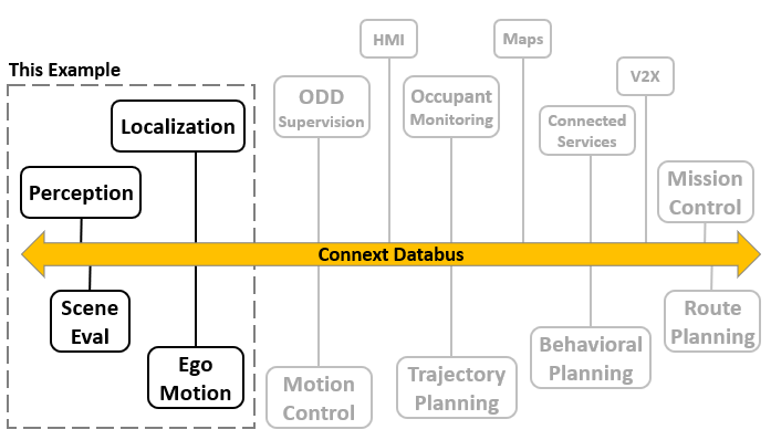
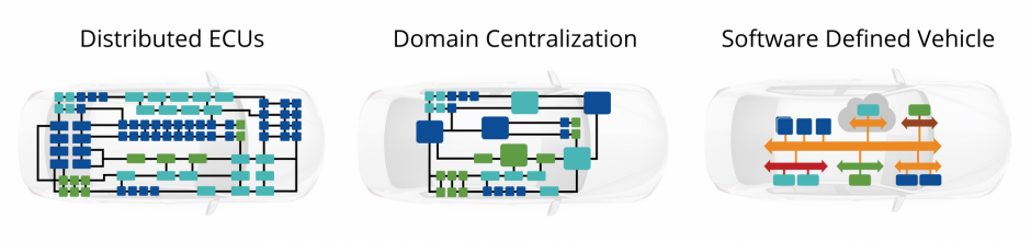
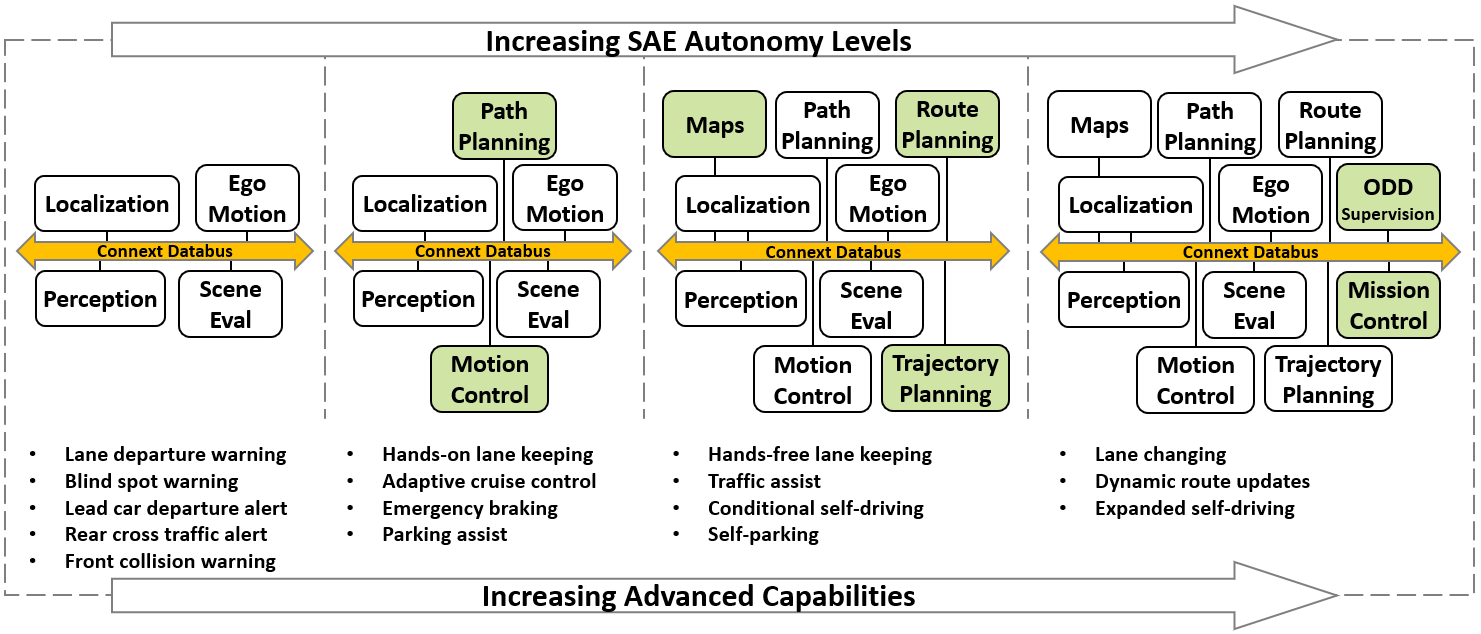
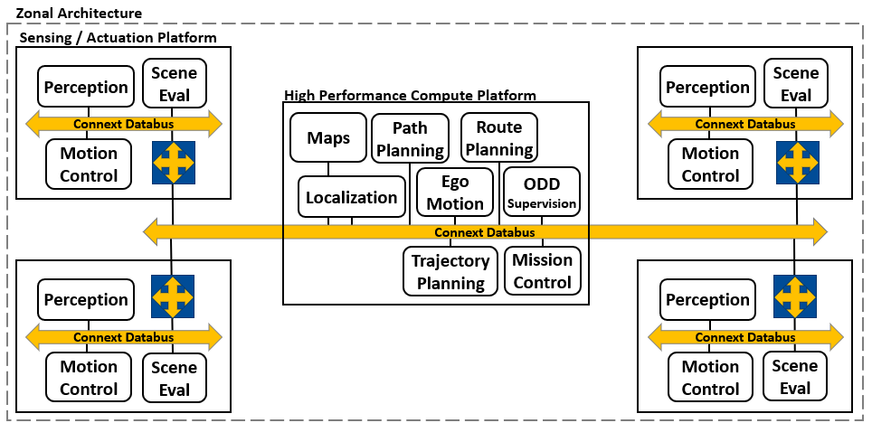
This example architecture supports the creation of driver-assistance features such as lane departure warning and blind-spot warning, while providing for future expansion into higher levels of autonomy. The application modules provide a high-performance data communications network within the Connext framework, freeing the developer to focus on creating the value within each module. The purpose of each application module can be described as follows:
Perception: The perception module is responsible for interpreting sensor data (Lidar, Radar, Cameras, etc.) to detect, classify, and track objects within its field of view. It produces a sequence of identified object descriptors which are provided to the Localization and Ego Motion modules for further processing.
Localization: The localization module is responsible for determining the precise location of the Ego Vehicle and its surrounding detected objects within a larger coordinate space, typically using GNSS/GPS as a global coordinate reference. It produces an ‘Ego Pose’ value indicating the position and orientation of the vehicle.
Ego Motion: The ego motion module is responsible for converting the sequence of Ego Pose values into a set of values describing the motion of the vehicle in all axes, including the velocity and acceleration of the vehicle.
Scene Evaluation: This module is responsible for interpreting the Ego Motion, Ego Pose, detected objects and other data to detect conditions such as lane departure, objects in blind spots, lead vehicle departure and others. This module may also predict the motions of surrounding objects to enable more advanced levels of autonomy.
In this example application, the sensor data used by the Perception module is provided by an additional application that generates test data. In actual use, this data would be provided by physical sensors.
 Success-Plan Services